What Is Fir Filter Design
The filter coefficients or taps of such filters obey either an even or odd symmetry relation.
What is fir filter design. Thus this is all about fir filter fir filter design logical structure and frequency response of fir filters. Due to not having a feedback loop an fir filter is inherently stable. Moreover the design and verification of finite impulse response fir low pass filter is exhibited based on the. The parks mcclellan method inaccurately called remez by matlab is probably the most widely used fir filter design method.
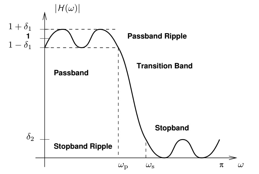
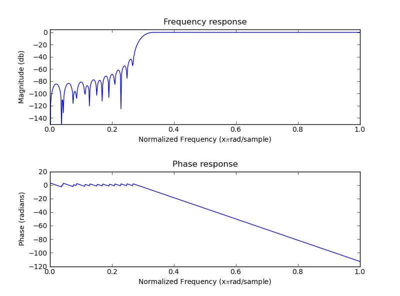
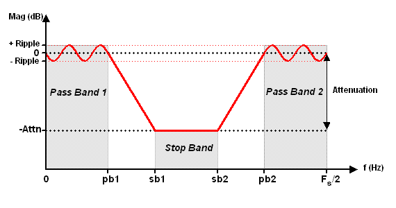
Then uses the finite impulse response to choose the preferred frequency. Depending on this symmetry and on whether the order n of the filter is even or odd a linear phase filter stored in length n 1 vector b has certain inherent restrictions on its frequency response. It is used in software radio that permits easily adaptable filters with good rejection and without changing hardware. The resulting pass band and stop band parameters are equal even though often the specification is more strict in the stop band than in the pass band unnecessary high accuracy in the pass band.
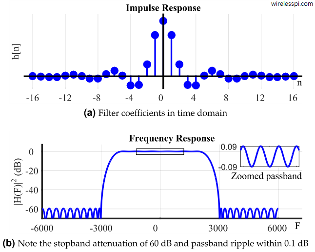
In effect more taps means more stopband attenuation less ripple narrower filters etc. Fir filters are normally non recursive meaning they do not use feedback and as such are inherently stable. An fir filter is designed by finding the coefficients and filter order that meet certain specifications which can be in the time domain e g. The three most popular design methods are in order.
Meanwhile for an iir filter we need to check the stability. Secondly an fir filter can provide a linear phase response. Finite impulse response or fir filters express each output sample as a weighted sum of the last n input samples where n is the order of the filter. It is an iteration algorithm that accepts filter specifications in terms of passband and stopband frequencies passband ripple and stopband.
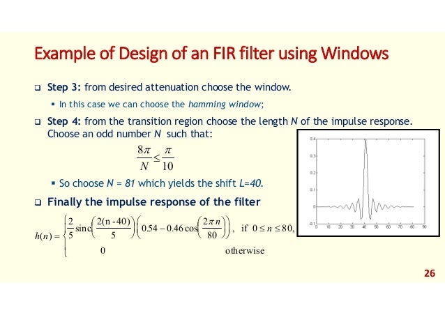
Fir filter design using windows fir filter design based on windows is simple and robust however it is not optimal. The number of fir taps often designated as n is an indication of 1 the amount of memory required to implement the filter 2 the number of calculations required and 3 the amount of filtering the filter can do. An fir filter is usually implemented by using a series of delays multipliers and adders to create the filter s output. 3 1 what are the methods of designing fir filters.
A matched filter and or the frequency domain most common. Firstly as shown in figure 2 there is no feedback loop in the structure of an fir filter. An fir filter has two important advantages over an iir design. A finite impulse response fir filter is a filter structure that can be used to implement almost any sort of frequency response digitally.
